
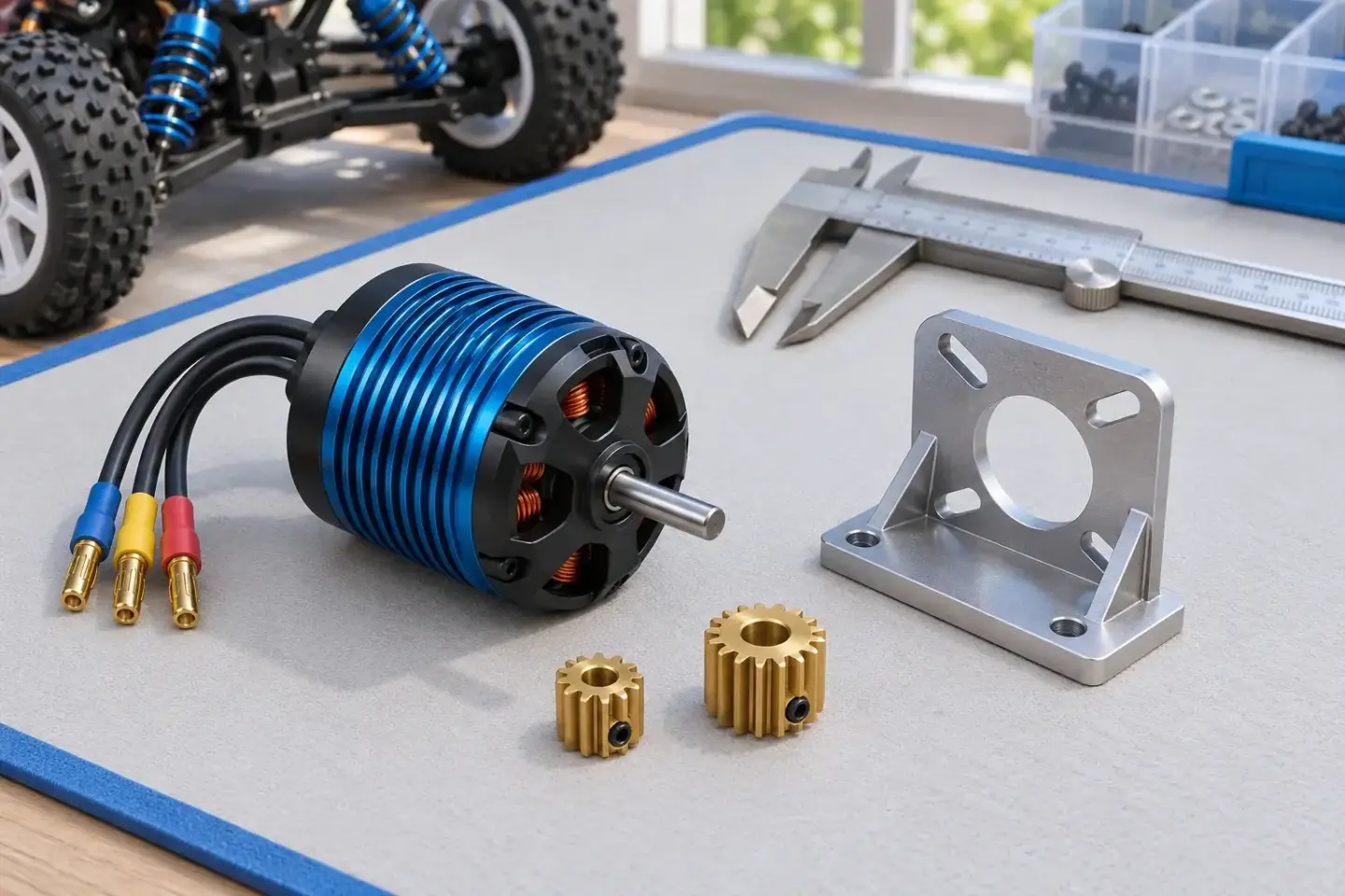
A brushless conversion is a chain of interfaces. The motor must fit the mount; the shaft must fit the pinion; the pinion must match the spur; the ESC must support the motor and battery; and the chassis must carry the assembly without restricting movement. “Same scale” does not establish any of those connections.
The former Blue Groove catalogue included brushless conversion kits and motor brackets. This article preserves that workshop subject without claiming that a historical kit is available or that its fitment list survives. Start with the exact chassis revision and the manufacturer’s current documentation for every proposed component.
Make the interface sheet before the shopping list
Draw four boxes: chassis, motor, ESC and battery. Under each, enter its exact model or part number. Put the unanswered questions between the boxes. A blank is useful: it identifies what a seller or manual must resolve before money changes hands.
- Motor to mount: mounting-hole pattern, motor diameter and length, screw specification, screw engagement and clearance behind the motor.
- Motor to pinion: shaft diameter, shaft length, flat location where applicable, pinion bore and the specified fastening method.
- Pinion to spur: compatible tooth system, tooth counts, usable adjustment range and correct alignment across the gear faces.
- ESC to system: supported battery configuration, motor limits, sensored or sensorless wiring requirements and receiver-power arrangement.
- Battery to chassis: physical fit, secure retention, connector compatibility and a lead route that clears gears and suspension.
Measure the actual available space with the body fitted. Include the fan, wires, connectors and room to remove the battery. A motor that fits an empty chassis may block a brace or place a solder joint against the shell after assembly. Do not drill or cut the chassis until fitment is established and the modification is within the platform’s supported options.
Keep gearing arithmetic visible
For a conventional single-stage pinion-and-spur drive followed by a fixed internal reduction, final drive ratio is spur teeth divided by pinion teeth, multiplied by the internal ratio. This describes that arrangement; other transmissions require their own calculation.
Illustrative calculation: a 72-tooth spur, 18-tooth pinion and 2.6 internal ratio give 72 ÷ 18 × 2.6 = 10.4:1. Changing only the pinion to 20 teeth gives 9.36:1. The lower numerical ratio means more wheel rotation per motor rotation. These invented numbers explain the arithmetic; they are not a recommendation for your car.
Record tyre diameter too. A bigger tyre travels farther per revolution, so keeping the same gears does not keep the same ground travel per motor revolution. This is one reason a conversion recipe for a small-tyred buggy should not be copied straight into a large-tyred truck.
Treat the ESC manual as a compatibility document
Hobbywing’s XERUN XD10 Pro instructions distinguish sensored wiring, where matching A/B/C connections matter, from sensorless wiring. They also specify battery, motor and BEC limits and advise removing the pinion during calibration. This is a model-specific example of the checks to make, not an ESC recommendation for a truck conversion. Read the XD10 Pro manual.
Find the equivalent information for your actual controller. Check the receiver and servo voltage limits before selecting a BEC setting. Establish how receiver power is supplied; do not combine power sources without a manufacturer-approved wiring arrangement. Confirm battery chemistry and protection settings before a powered test.
First run: answer a small question
The first task is to confirm controlled operation, not to find top speed. Complete the manufacturer’s calibration and fail-safe procedure with the drive system made safe. Then use a clear area, conservative supported settings and short runs. Recheck fasteners, mesh, wire routing and component temperatures between runs.
Use the temperature limits and measurement method specified for your motor and ESC. An infrared case reading, a built-in sensor and a finger touch are different observations. Do not translate one into another or borrow a universal temperature ceiling from an unrelated controller. The XD10 Pro manual explicitly links aggressive timing and gearing with thermal risk; its numerical limits belong to that product. Hobbywing’s timing and temperature cautions.
If the system cuts out, inspect and identify the recorded fault before trying again. A protective shutdown is useful diagnostic information. Repeatedly resetting it without finding the cause defeats the purpose of the check.
What counts as a finished conversion?
Keep a final parts list, wiring photograph, gear calculation and baseline settings. Record the surface, run duration and where temperatures were measured. The useful outcome is a car that can repeat its intended task within the documented limits. A brief wheelspin on a stand proves much less.
Historical reference: Jammin CRT .5
The original product entry numbered 29859 survives in a 25 January 2009 archive as a Jammin CRT .5 Electric Conversion Kit, code ECON 2, with short and extended chassis options. This identifies the former link target. It does not establish present availability or certify a used kit’s completeness. Original archived product page.
Keep the chassis option with any part identification. The archived sales description and comments are historical material, not current instructions for substituting a motor, battery or servo. Use the interface sheet above to document the equipment actually in front of you.
Historical reference: Revo E-CON
The former product entry 29847 is preserved in a 25 January 2009 snapshot as Nitro Crusher Revo E-CON, code ECON 1. The original page describes an electric conversion kit for Revo chassis and lists a motor bracket, trays and associated hardware. That establishes the identity of the incoming link, not a present-day compatibility guarantee. Original Revo E-CON page.
The sales copy includes old configuration and performance claims. They are not adopted here as current recommendations. Identify the actual chassis, transmission and electronics before assessing a surviving kit.